> For the complete documentation index, see [llms.txt](https://help.smvend.io/llms.txt). Markdown versions of documentation pages are available by appending `.md` to page URLs; this page is available as [Markdown](https://help.smvend.io/equipment-installation/bill-and-coin-acceptors/azkoyen-u-ii-hopper.md).
# Azkoyen U II hopper
Below you can find the guide on how to connect the Azkoyen U-II hopper with the SmVend Smart Connector controller.
### Step-by-step guide
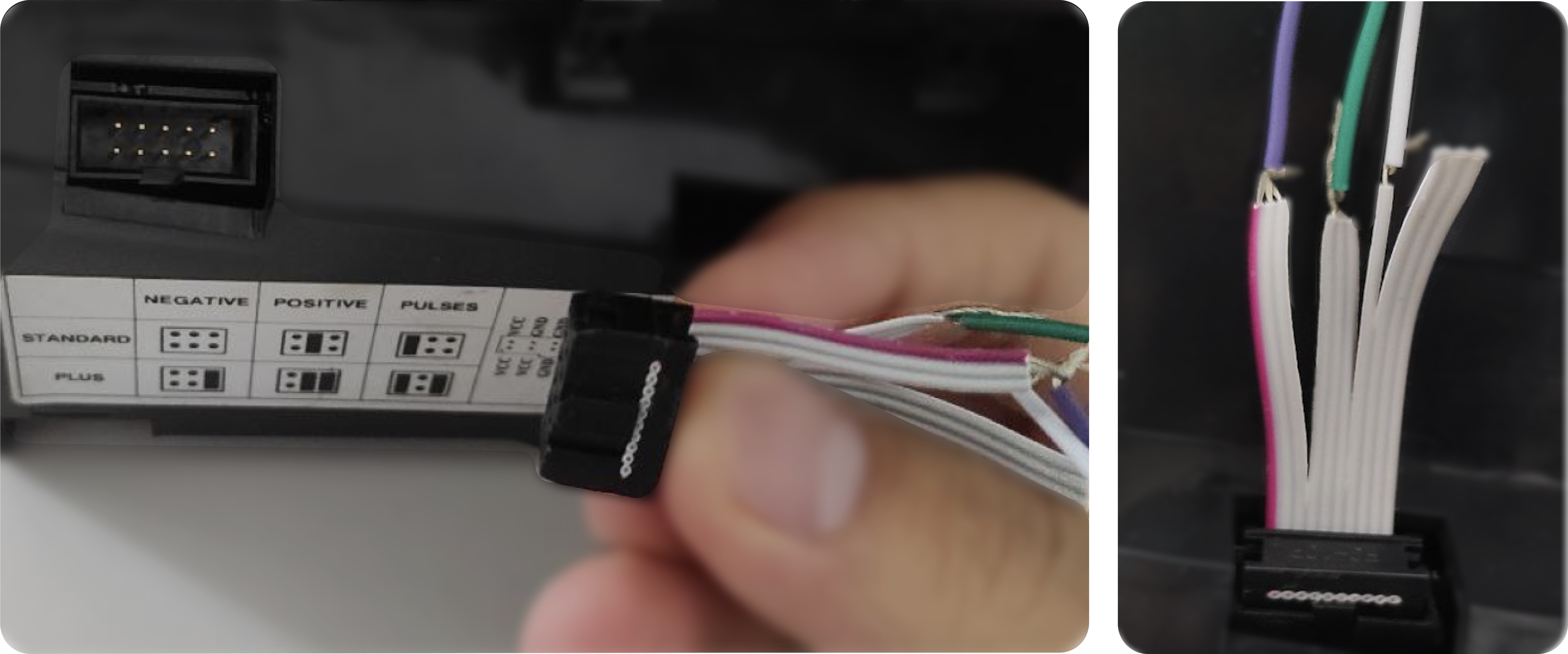
1. **Switch the hopper to the STANDARD PULSE mode**\
To switch the Azkoyen U-II hopper to pulse mode, you need to install a jumper at the underside of the hopper as shown in the illustration in accordance with the instructions indicated on the machine.
| | |
| ------------------------------------------------------------------- | ------------------------------------------------------------------- |
2. **Connect the power supply cable and pulse output to the hopper** \
Contacts 1, 2, 3 are combined into one — this is +12V.\
Contacts 4, 5, 6 are combined into one — this is GND.\
Contact 7 (“Control”) is used to transmit the pulse and deliver the change from the hopper.\
The other contacts are not used.
|
| |
| ---------------------------------------------------------------------------------------------------------------------------------------------------------------------------------------------------------------------------------- | ------------------------------------------------------------------- |
3. **Connect everything to the SmVend telemetry controller**\
Connect the coin acceptor, hopper, output motor, and output sensor to the SmVend telemetry controller and an external +12V power supply according to the following scheme.
* **Coin acceptor**\
The +12V power supply wire from the coin acceptor is connected to the ENABLE terminal.\
The PULSE wire from the coin acceptor (signal wire) is connected to the COIN terminal.\
The GND wire from the coin acceptor is connected to the GND terminal.
* **Output motor**\
The +12V power supply wire from the output motor is connected to the +12V terminal.\
The GND wire from the output motor is connected to the OUTPUT1 terminal.
* **Output sensor**\
The +12V power supply wire from the output sensor is connected to the +12V terminal.\
The GND wire from the output sensor is connected to the CARD terminal.
{% hint style="warning" %}
**Attention!** The output sensor must be closed (short-circuit the input to the ground) at the time of the product's passage.
{% endhint %}
* **Hopper**\
The +12V power supply wire from the hopper is connected to the +12V terminal.\
The PULSE wire from the hopper (signal wire) is connected to the OUTPUT2 terminal.\
The GND wire from the hopper is connected to the GND terminal.
* **External power supply +12V**\
The +12V power supply wire from the external power supply is connected to the +12V terminal.\
The GND wire from the external power supply is connected to the GND terminal.
4. **GSM antenna** \
After connecting the telemetry controller to the machine, a GSM antenna must be connected to amplify the GSM signal. Ensure that a SIM card is installed in a designated slot.
5. **Configuration in the SmVend personal account**\
Next, you need to configure the telemetry controller through your [**SmVend personal account**](https://app.smvend.io/)**:**
* Go to the specific machine page
* Go to the `Configuration` tab
* Set the cost of 1 unit of product in the `Price` field
* Set the cost of 1 pulse in the `Input pulse price for input 2 (coins)`field
* Set the change value in the `Input pulse price for input 3 (acquiring)` field
* Enable the `Hopper mode (enable output 1 until pulse on input 3)` option
* Click `Save` for the settings to be transmitted to the telemetry controller
* Go to the `History` tab and check that the settings were applied on the telemetry controller. If the `Completed` column contains:\
— the settings are applied \
 — the settings have not been applied yet.
6. **Restart the machine**\
Restart the machine's power supply after switching to the hopper operation mode.